|
ESP32-PC - Page 2 |
|
ESP32-PC - Page 2 |
There are currently two peripherals connected to the machine. A keyboard and a monitor. The keyboard is a custom built mechanical keyboard, with a compact yet plentiful layout. The monitor, as briefly described in the Introduction, is a VGA monitor connected to the display ESP32 controller.
VGA is an analog signal, sent over 6 wires. 3 for R,G,B, one for horizontal sync signal that indicates end of scan line, vertical sync signal that indicates the end of frame, and ground.
Since the ESP32 generates a digital signal, a digital to analog converter (DAC) is needed. The ESP32Lib implementation supports multiple resolution and color depths. A full color depth requires 8 bit for each of the R,G,B channels, and is not feasible with this microcontroller. Testing the implementation in various modes, I finally decided to use a low color depth mode, using only 2 bits per channel. This makes a 6 bit color space, which is 64 colors. Surprisingly, this is still quite a good coverage of the color range, as can be seen in this palette.

As can be seen, since it's 2 bits per color, the diagonal of the palette shows 4 gray levels: Black, Dark gray, Light gray, and White. The DAC used to convert the 2 bits of each channel into an analog signal is a simple resistor ladder.
Since the color space is 6bit, the frame buffer format is 1 byte per pixel, where the lower 6 bits in the byte contain the color information.
According to Bitluni, the ESP32Lib natively supports up to 800x600 resolution, but since it's using double buffering, there needs to be enough RAM to hold 2 frame buffers with the screen resolution. With 800x600, this means 937.5KB The ESP32 board I used for this purpose only has 512KB, and not all of it can be dedicated to the frame buffer. I eventually settled on a resolution of 400x300, which consumes 234KB.
Since there is no easy way to connect a USB keyboard, and it wouldn't be fun to use a ready made one, I decided to build a keyboard for this machine. The design is a standard mechanical keyboard with a 5x15 matrix. Since there is lots of documentation on the web of how to build one, I will not go into all the details of why diodes are needed to prevent ghost keys and such. The basic idea is that each key is a an on/off button, and applying voltage to the rows and sampling the columns, or vice-versa.
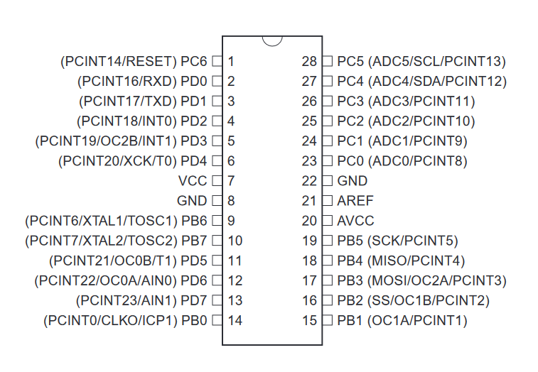
The keyboard also has its own microcontroller, but since the task is limited and simple, the selection is not difficult. The only real requirement is the number of GPIO pins available. The selected controller in this case is the popular ATMega328P. It has the 20 pins needed to drive and sample the matrix rows and columns, with left over for ICSP programming and a UART output.
The controller continuously applies voltage and samples which key in the matrix are pressed. As soon as a change is detected in the state of any key, the scan code of the key is sent over the UART. When the key is released, the scan code is sent ORed with 0x80. Scan codes are simply index of the key in the matrix, starting from the top left and incrementing along the first row and so on. The top left key of Esc has a scan code of 0, so when Esc is pressed, a byte of 0 is sent, and when the key is released, a value of 0x80 is sent. It's the job of the operating system to translate the scan codes into useful key values. The keyboard connection schema is relatively simple, though packed with components, with all the keys.
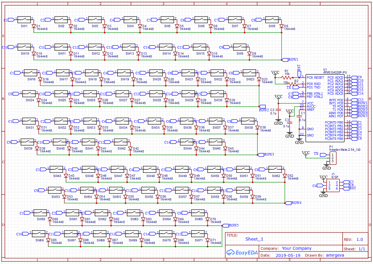
As can be seen, all the ATMega328P pins are assigned, and the MISO, MOSI, SCK lines of the ICSP programming protocol are shared with the column lines.
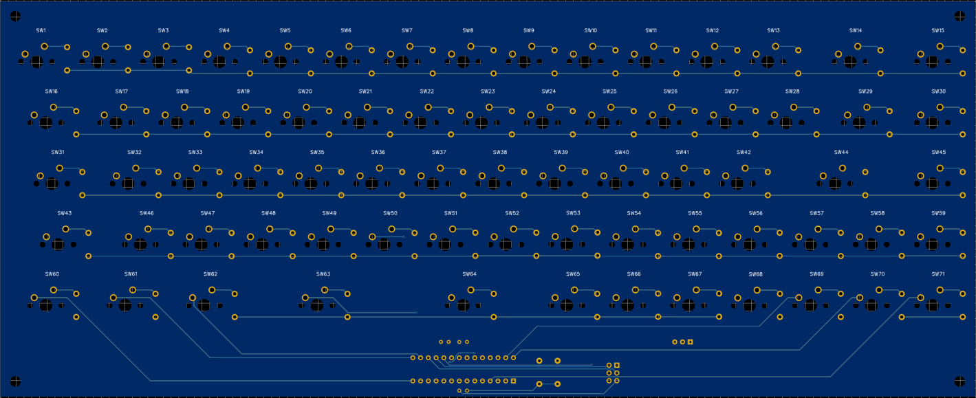
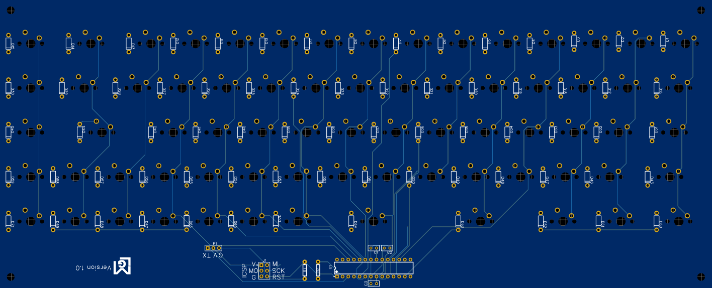
The PCB below clearly shows the lines for the rows and columns of the matrix.