 |
Z80-PC - Page 2 |
|
Z80-PC - Page 2 |
Now that we have our CPU and memory, it’s time to see how they connect together. The memory is like a large array of bytes, and the CPU has to tell it which byte it wants to read from or write to. In order to do this, the CPU sets the values of the A0 – A15 pins to compose a 16 bit binary number that represents the address (therefore A) in memory. 16 Bits cover exactly 64KB range of values. These pins together are called the Address Bus. The data that goes from or to the memory, is then placed on the D0 – D7 pins which constitute the Data Bus.
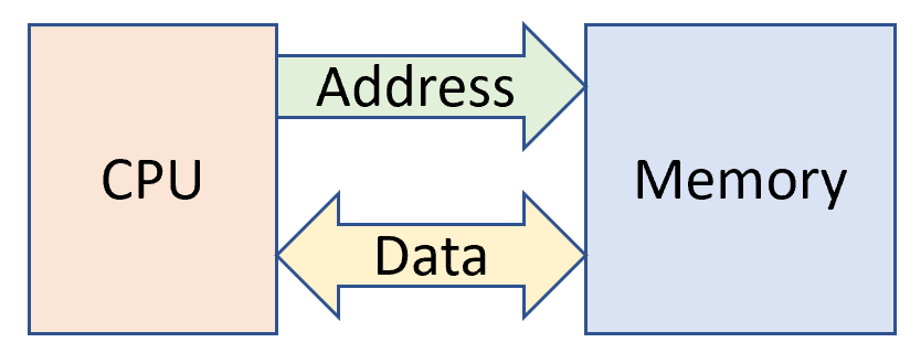
Note that the Address bus only goes one way, which means the CPU outputs the address, and the memory inputs the address. Due to electrical considerations, this is the simplest form of communication between components. The Data Bus, however, is more complicated, since the data can potentially be output by both the CPU (when writing) and memory (when reading). Having both output at the same time is a “No no”, and therefore there is a mechanism to make sure this doesn’t happen. The memory has a pin marked OE with a bar on top. The top bar indicates that the pin is “Active Low”. OE means output enable, which indicates to the memory chip that it can write to the data bus. The CPU has a pin called RD (with a bar), which indicates that the CPU wants to read the data bus. Therefore, connecting these two will ensure the synchronization we want. The memory also has a CS (chip select, active low) pin which enables the memory in the first place. This is there to allow the address bus to be used for other purposes, such as IO. Connecting the CS pin to the CPU’s MREQ (memory request, active low) pin takes care of that.