 |
Z80-PC - Page 5 |
|
Z80-PC - Page 5 |
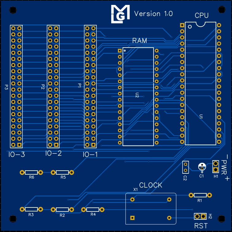
Since the IO devices are located on separate PCBs, the main board should contain the bare essentials of the system. This means that the CPU, RAM, Clock and expansion ports should populate the board.
The schematic described earlier is converted into a PCB design
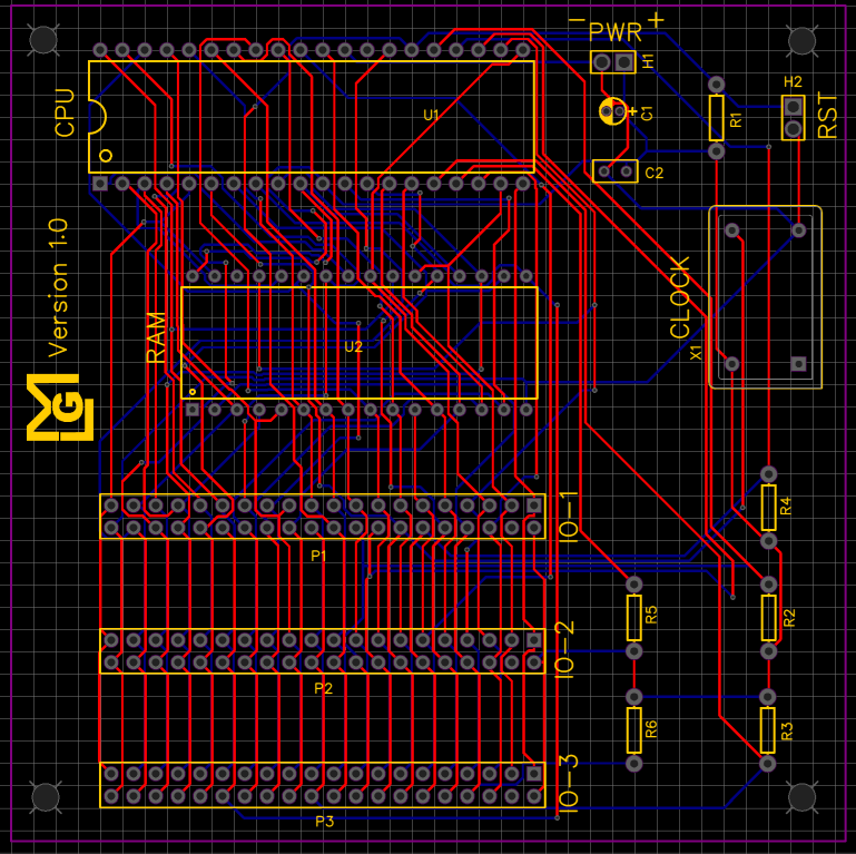
And after arranging the layout and running the auto-routing, the following PCB results:
The power and reset headers are populated with male headers which are later connected by wires to the appropriate switch / button.
The expansion ports are female headers which accept matching male connectors on the expansion cards.